The Controllers
The lights are all LED’s which means I don’t have to mess with any mains voltages and makes the display much safer. As most DIY controllers are built to work with mains voltage as is standard practise when used for outside displays, the controllers I use are customised to my needs.
The very first display ran on a simple parallel relay card with 8 channels. This proved the popularity of the Christmas Lights, and so a more expandable system was sort for the display in the coming years. I initially settled on the ICICLE system, which is a PIC based controller that connects to the PC using a serial port and provides 8 channels per board. The key factor was that the boards could be daisy chained together, and over the years I built 8 boards to provide 64 channels. The ICICLE boards ran the display at Selby College from 2008 – 2011.
I continued to use the ICICLE boards for the display at Selby College (until 2011), and for the lights in the Computer Science department at The University of York I built an Olsen 595 controller. This board has 64 channels per board, can also be daisy chained together but connects via parallel port to the PC instead of serial. A single board controls the entire display.

This is one of the modified ICICLE boards I used. If you look at the original design, you can see that the AC parts of the board have been replaced with a simple transistor circuit to control the LED’s and power them with DC voltage. I no longer use the ICICLE boards, having moved both displays to the Olsen 595 controllers. The reason for this change is the flexibility given by the 595 board, and the large DIY following means lots of information is available online. Also, one board provides 64 channels, and is much cheaper to build.

This is one of the modified Olsen 595 boards used. These boards aren’t modified quite as much as the ICICLE boards, and visually look the same. On the reverse of the board are some extra tracks which bring power to the RJ45 connectors to power the attached LED’s directly. Normally this board would connect to smaller individual boards via the RJ45 sockets which each have 4 SSR (solid state relays) to control AC circuits.
For the 2014 display, I’ve added a Renard Plus 32 controller which gives dimming capabilities on 32 channels. The Renard board is used to control the singing face silhouette, plus the village scenes.
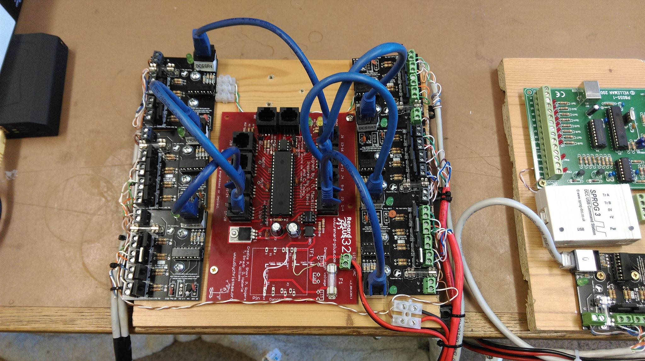
It connects via a serial port, and loads are attached via solid state relays with 4 SSR’s per break out board.
The Lights
LED’s are used on both display sets. A combination of single red, green and blue and RGB LED’s are used with over 300 in total. I also use some DMX lighting equipment, primarily used for disco’s and theatre shows.
Pingback: Work begins on the 2012 lights! « Deans Christmas Lights